Aluminium/cppper XLPE Armoured Power Cable (25-630mm2 11kv/12kv/15kv/18kv/20kv/33kv/35kv/66kv)
Application
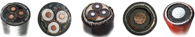
Medium voltage armoured cable refers to a type of electrical cable designed to transmit power at medium voltage levels while providing mechanical protection.in various applications, such as industrial plants, utility substations, power distribution networks, and construction sites.
| Voltage: | 0.6/1kv, 1.8/3KV, 3.6/6KV, 6/10KV, 10KV, 11KV, 15kv, 8.7/15KV, 18/30KV, 19/33KV, 26/35KV |
| Conductor: | Aluminum or Copper or Tinned Copper for class 2 |
| Insulation: | XLPE |
| Size of area: | 25mm2, 35mm2, 50mm, 70mm, 95mm2, 120mm2, 185mm, 240mm2, 300mm2 400mm2, 630mm etc. |
| Coroe: | Single Core or Three Core |
| Armour type: | 1. Galvanized steel wires/steel tape for 3 core; |
| 2. Stainless steel wire/Steel tape or Aluminium wire/tape for single core Polyvinyl chloride (PVC) or PE, or HDPE. | |
| International Standard: | Bs6622, Bs7835, Bs7870, ASTM, IEC Etc or according to your requirement. |
10kV, 11kV, 20kV, 30kV and 33kV cables are available in the following cross-sectional size ranges
| 10kV single core | from 35mm2 to 500mm2 |
| 10kV 3-core | from 35mm2 to 240mm2 |
| 11kV single core | from 50mm2 to 1000mm2 |
| 11kV 3-core | from 35mm2 to 400mm2 |
| 20kV single core | from 50mm2 to 500mm2 |
| 30kV single core | from 50mm2 to 500mm2 |
| 33kV single core | from 70mm2 to 1000mm2 |
25-630mm2 Medium Voltage Cable Single Core Parameter Data
Armoured Medium Voltage power cables can be supplied with copper conductors or with aluminium conductors upon request to the same standard. The copper conductors are stranded (Class 2) whereas the aluminium conductors are compliant to the standard using both stranded and solid (Class 1) constructions.
| CONDUCTOR SIZE | ONDUCTOR DC RESISTANCE AT (200 C Ω/Km) | CAPACITANCE mF/Km | CHARGING CURRENT (A/Km) | DIELECTRIC LOSSES (W/Km) | LAID IN GROUND A | LAID IN DUCT A | LAID IN FREE AIR A |
| 70 | 0.268 | 0.303 | 0.605 | 15.35 | 277 | 227 | 313 |
| 95 | 0.193 | 0.332 | 0.662 | 16.81 | 329 | 277 | 376 |
| 120 | 0.153 | 0.362 | 0.723 | 18.37 | 370 | 308 | 430 |
| 150 | 0.124 | 0.397 | 0.793 | 20.15 | 412 | 345 | 484 |
| 185 | 0.0991 | 0.43 | 0.859 | 21.81 | 460 | 390 | 546 |
| 240 | 0.0754 | 0.483 | 0.964 | 24.47 | 520 | 451 | 629 |
| 300 | 0.0601 | 0.535 | 1.068 | 27.13 | 571 | 507 | 708 |
| 400 | 0.047 | 0.592 | 1.181 | 30 | 609 | 564 | 777 |
| 500 | 0.0366 | 0.666 | 33.76 | 33.76 | 661 | 631 | 863 |
| 630 | 0.0283 | 0.76 | 1.516 | 38.51 | 707 | 698 | 945 |