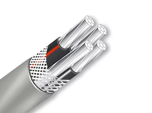
Service Entrance Cable
Construction
Voltage
0.6/1kV
Conductor
Copper, AAC, AAAC, Copper clad aluminum
Insulated
XLPE/PVC/PE
Out Sheath
PE/PVC
Application
Service entrance cables are typically installed underground or overhead, connecting the electric meter on the exterior of the building to the main electrical panel or load center inside. They serve as the primary connection point between the utility’s power lines and the electrical system of the building.
Feature
Service entrance cable is specifically designed to handle the high voltage and current levels required for supplying electricity to the premises. It is constructed with multiple conductors, including phase conductors (usually black, red, or blue insulated wires), a neutral conductor (typically white or gray insulated wire), and sometimes a bare copper or green-insulated grounding conductor.
The conductors are typically made of copper or aluminum, with copper being more common due to its superior conductivity.
Standard
IECA Standard, NFC Standard.
| Conductor | Stranding | Nominal O.D. (Mils) | Allowable Ampacities | Approximat e Net Weight Per 1000′ (Lbs) | Standard Package | ||||
| Size/Const. AWG or kcmil | Phase Conductor Neutral | Equipment Ground Conductor | 60°C | 75°C | 90°C | Dwelling | |||
| 8-8-8 | 7 | — | 586 | 40 | 50 | 55 | — | 231 | B |
| 6-6-6 | 7 | — | 669 | 55 | 65 | 75 | — | 338 | B |
| 4-4-4 | 7 | — | 764 | 70 | 85 | 95 | 100 | 498 | B |
| 3-3-3 | 7 | — | 829 | 85 | 100 | 110 | 110 | 611 | B |
| 2-2-2 | 7 | — | 896 | 95 | 115 | 130 | 125 | 752 | B |
| 1-1-1 | 19 | — | 1021 | 110 | 130 | 150 | 150 | 948 | C |
| 1/0-1/0-1/0 | 19 | — | 1114 | 125 | 150 | 170 | 175 | 1169 | C |
| 2/0-2/0-2/0 | 19 | — | 1209 | 145 | 175 | 195 | 200 | 1444 | C |
| 3/0-3/0-3/0 | 19 | — | 1317 | 165 | 200 | 225 | 225 | 1792 | C |
| 4/0-4/0-4/0 | 19 | — | 1438 | 195 | 230 | 260 | 250 | 2226 | C |
| Conductor | Stranding | Nominal O.D. (Mils) | Allowable Ampacities | Approximat e Net Weight Per 1000′ (Lbs) | Standard Package | ||||
| Size/Const. AWG or kcmil | Phase Conductor & Neutral | Equipment Ground Conductor | 60°C | 75°C | 90°C | Dwelling | |||
| 8-8-8-8 | 7 | 7 | 645 | 40 | 50 | 55 | — | 286 | B |
| 6-6-6-6 | 7 | 7 | 738 | 55 | 65 | 75 | — | 424 | B |
| 4-4-4-6 | 7 | 7 | 844 | 70 | 85 | 95 | 100 | 585 | B |
| 3-3-3-5 | 7 | 7 | 910 | 85 | 100 | 110 | 110 | 719 | B |
| 2-2-2-4 | 7 | 7 | 984 | 95 | 115 | 130 | 125 | 887 | B |
| 1-1-1-3 | 19 | 7 | 1132 | 110 | 130 | 150 | 150 | 1117 | C |
| 1/0-1/0-1/0-2 | 19 | 19 | 1235 | 125 | 150 | 170 | 175 | 1382 | C |
| 2/0-2/0-2/0-1 | 19 | 19 | 1342 | 145 | 175 | 195 | 200 | 1713 | C |
| 3/0-3/0-3/0-1/0 | 19 | 19 | 1462 | 165 | 200 | 225 | 225 | 2129 | C |
| 4/0-4/0-4/0-2/0 | 19 | 19 | 1598 | 195 | 230 | 260 | 250 | 2650 | C |
| Conductor | Stranding | Nominal O.D. (Mils) | Allowable Ampacities | Approximat e Net Weight Per 1000′ (Lbs) | Standard Package | ||||
| Size/Const. AWG or kcmil | Phase Conductor & Neutral | Equipment Ground Conductor | 60°C | 75°C | 90°C | Dwelling | |||
| 10-10-10 | 1 | 12 | 428 X 283 | 30 | 30 | 30 | — | 127 | ABC |
| 8-8-8 | 7 | 8 | 587 X 380 | 40 | 50 | 60 | — | 211 | ABC |
| 6-6-6 | 7 | 12 | 659 X 416 | 55 | 65 | 75 | — | 308 | BCE |
| 4-4-4 | 7 | 12 | 815 X 506 | 70 | 85 | 95 | 100 | 471 | BCE |
| 3-3-3 | 7 | 12 | 883 X 548 | 85 | 100 | 110 | 110 | 583 | B |
| 2-2-2 | 7 | 15 | 994 X 578 | 95 | 115 | 130 | 125 | 718 | BD |
| 1-1-1 | 19 | 14 | 1093 X 664 | 110 | 130 | 150 | 150 | 904 | B |
| 1/0-1/0-1/0 | 19 | 19 | 1179 X 707 | 125 | 150 | 170 | 175 | 1123 | BC |
| 2/0-2/0-2/0 | 19 | 18 | 1283 X 767 | 145 | 175 | 195 | 200 | 1379 | BC |
| 3/0-3/0-3/0 | 19 | 14 | 1429 X 862 | 165 | 200 | 225 | 225 | 1712 | BC |
| 4/0-4/0-4/0 | 19 | 18 | 1541 X 918 | 195 | 230 | 260 | 250 | 2146 | BC |
| Conductor | Stranding | Nominal O.D. (Mils) | Allowable Ampacities | Approximat e Net Weight Per 1000′ (Lbs) | Standard Package | ||||
| Size/Const. AWG or kcmil | Phase Conductor & Neutral | Equipment Ground Conductor | 60°C | 75°C | 90°C | Dwelling | |||
| 6-6-8 | 7 | 8 | 659 X 416 | 55 | 65 | 75 | — | 281 | BC |
| 4-4-6 | 7 | 12 | 790 X 481 | 70 | 85 | 95 | 100 | 420 | BC |
| 3-3-5 | 7 | 12 | 843 X 508 | 85 | 100 | 110 | 110 | 515 | BC |
| 2-2-4 | 7 | 12 | 929 X 563 | 95 | 115 | 130 | 125 | 639 | BC |

